Features
IG-SBB-SA
Introduction
IG-SBB-SA Bends Spacer Bars Semi-Automatically


It is specially designed to bend 90 degrees faster and easier.
Highlights

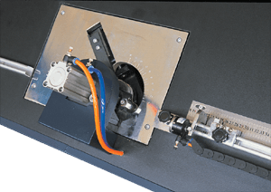
- Sophisticated bending tool and support rollers allow spacer bending corners in perfect shape and good looking. Corners are dimensionally stable and are non-distorted.
- Thanks to advanced cutting tool and technology, no burr or chip are found on cutting edges. It does not affect joint quality between spacer bars. This bending machine can also act as cutting machine in case necessary.
Structure
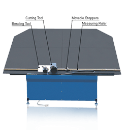
It Consists Of Incline Table, Bending System, Measuring Ruler Gauges & Stoppers, Cutting & Control System

Incline table is a structure where spacer bars are bent and lean. Bending system is composed of bending tools, support rollers and pneumatic system. Measuring ruler gauges are used as guidelines for two stoppers moved to proper positions. Cutting system includes motorized cutting blade to cut spacer bar instantaneously.
Procedure

- One stopper is moved along measuring gauge and is rest at position of spacer frame length. Another stopper is moved until it rests at position of spacer frame width.
- Spacer bar is then feed manually into the bending machine until it arrives at first stopper. Foot pedal is pressed and bending begins.
- Spacer is feed again until it arrives at second stopper. Foot pedal is pressed and second bending begins.
- Cycle begins until all bending are completed.
- Spacer is then finally cut in exact length.
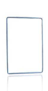
- One end of spacer is already inserted with a straight connector. Operator is required to insert the connector to the other end. A complete spacer frame is then achieved.
- Spacer begins to feed to the machine again and the cycle is repeated.
- When spacer bar comes to an end, next piece of spacer bar is loaded manually. Front end of subsequent spacer is connected manually to the tail end of prior spacer by means of straight connector. It minimizes spacer wastage.