Features & Specs
- Introduction
- Features
- Specifications
- Options
Options
Loading Machines
Tilting Arms Loading Systems
Two designs are available.
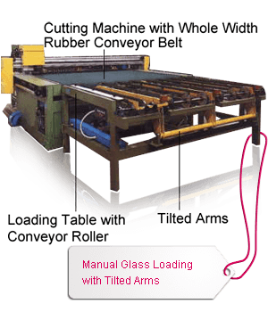
- Manual Glass Loading with Tilted Arms
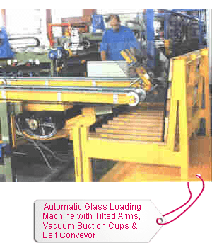
- Automatic Glass Loading Machine with Tilted Arms, Vacuum Suction Cups & Belt Conveyor
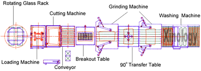
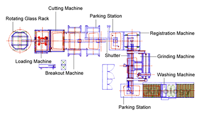
Overhead Glass Loading System
This system consists of three major devices,
- Glass Rack Rotating Table
- Automatic Overhead Loading Machine
- Belt Conveyor
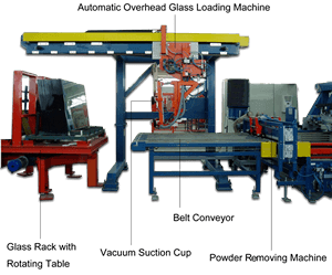
Rotating Table
This turntable comes with two glass racks. It is driven by an AC frequency controlled motor for 180 degree rotation. The table rotates on a solid geared ring with integrated ball bearing.
Automatic Overhead Loading Machine
This loading machine comes with tilting structure and vacuum suction cups. It is mounted on a shuttle system running on linear bearings. The shuttle is driven by a frequency controlled AC geared motor. The shuttle carries a 90 degree tilting device driven by a pneumatic cylinder on which four bellow suckers are mounted. Two suction cups are adjustable according to glass sizes. Frame structure mounted with suction cups could be rotated + or - 90 degree by means of a motor. It is used to load glass from glass rack located on rotating table. Loading machine moves towards glass rack by means of shuttle. Suction cups hold glass and loading machine moves back to where it comes from. Loading arms then tilts 90 degree downwards. It descends and brings glass onto a conveyor. When glass on one side of glass rack is empty, table turns until another side full of glass faces to loading machine. The equipment comes with a vacuum pump system.
Belt Conveyor
Conveyor is driven by a frequency controlled AC-geared motor. Loading machine brings glass on this belt conveyor. This belt conveyor brings glass to subsequent loading and registration conveyor or optional powder removing machine.
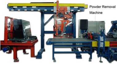
Powder Removing System
Glass is sometimes sprayed with powder or anti-mildew agent for packing and transportation purposes during float glass production process. It is necessary to be removed prior to cutting. One of the most popular powders or agent is Lucite. Power removing system is used to brush off powder or Lucite. It consists of top and bottom cylindrical brushes which are mounted in a trolley with wheels. The freely movable structure allows pulling the complete brush-systems sideways out of the line for inspection, adjustment, cleaning or replacement of brushes. Each cylindrical brush is driven by its own AC-motor. Both brushes are covered with vacuum hoods and nozzles, where flexible vacuum tubes are connected to. The brushes with their motors and vacuum hoods are adjustable in height on both sides. The system comes with a vacuum collecting device where removed powder or Lucite is collected properly.
Drilling
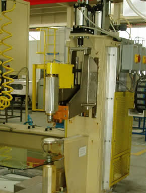
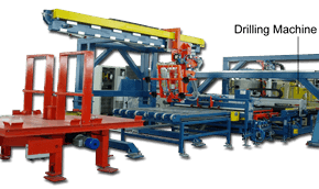
- Holes drilling are usually required for sidelites, ventilators and backlites. The drilling machine consists of two single spindles, one top and one bottom.
- The main frame of the drilling head is fabricated from structural rectangular tubing and steel plate which is then thermally stress relieved, sandblasted and precision machined.
- On the back of the main frame, linear rails are mounted. These rails form the axis of motion for the upper and lower spindle arms. The spindle arms are also fabricated from rectangular tubing and stress relieved, sand blasted and machined. The arms bolt on to the upper and lower slides formed by the rail bearings and arm mounting plates. This forms a strong rigid member to mount the spindles and motors.
- Each spindle arm and slide arrangement is driven up and down by an air cylinder. The air cylinders are connected to the spindle arms by alignment couplers and drive rods. Each spindle arm uses a hydraulic feed check to control spindle feed rate during drilling. Holes chamfering can be achieved by slowing down the feed in the feed check.
- Water used for coolant is fed through the center of the spindle shaft to the core drill. A rotary fitting connects the spindle shaft to the water supply. Spindle bearings are isolated from the water. The rotary fitting is a wear item which is easily replaced rather than the internal face seals of the spindle.
- Spindle shafts are mounted in precision ball bearings which are pre-loaded for accuracy. Spindle bearings are lubricated by an oil mist system which is activated any time the spindles are running. Spindles are individually driven by 1 H.P., A.C. motors which are mounted at the back of the main frame. The speed of the motors is controlled by an AC frequency drive. The speeds are selected in the operator control panel interface. Poly v-belts are used to drive the spindles.
- Also attached to each spindle arm is a positive depth stop. These stops are screw type adjustments and are used to set the penetration of both the top and bottom drills. The fixed half of the stop is insulated from the frame and supplied with 12 volts of A.C. current. When contacted by the movable half, a circuit is completed and the spindle reverses directions. This feature eliminates the need of limit switches, etc., which are subject to failure in this environment.
- A similar insulated probe is made when the spindles are fully retracted, signaling for coolant shut off, drill unclamp, and end of cycle.
- Diamond core drills are mounted into the drill spindles via quick change collets for fast change of diamond core drills. These collets are made of stainless steel and accept a standard 3/8 inch drill shank.
- Wiring between the drill head and operator human-machine interface will be furnished in non-metallic conduit. Speeds and feeding are pneumatically controlled.
- Drill heads come with a 20” throat. Glass thickness ranges from 3 to 12 mm. Hole diameters are from 6 to 50 mm. Maximum misalignment distance between top and bottom drill centers is 0.05mm. Throat depth is 500 mm.
Powder Applying Machine
This option is required when preprocessed glass is for windshield. The machine is a spraying design enclosed inside a chamber across and above outlet conveyor rollers of washing machine. Powder is spray under control so that powder film thickness on glass surface is consistent and even. The powder is used to prevent pair of glass from sticking to each other during subsequent bending.
Centrifugal Separating Machine
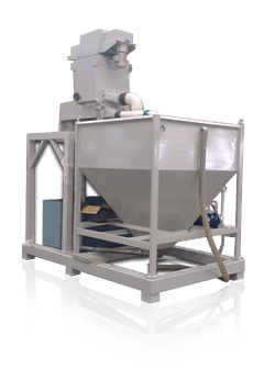
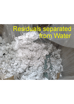
It is a liquid and solid centrifugal separating machine used to separate residual from liquid by means of centrifugal force. Recycling liquid drains from grinding and polishing machines to separating machine directly. The centrifuge works in line with glass grinding and polishing machines and separates residual from liquid in real time. Cleaning of water tank is no more required.
Others
Various designs for automotive glass pre-processing are also available depending on budget, automation, workforce and spaces, etc.
