Features & Specs
- Introduction
- Features
- Specifications
- Options
Features
Loading Conveyor
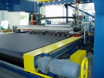
Glass is loaded on this conveyor manually. The conveyor is also a registration station to have glass in proper position before traveling to subsequent cutting machine. The conveyor is driven by a frequency controlled AC-geared motor. It is integrated in a belt conveyor with a lifting table for glass support during registration. There is a retractable fixed front stops for leading edge registration. Adjustable stops with digital positioning indicator are used for manual registration for glass side edges.
CNC Cutting Machine
- It consists of a full width belt conveyor, cutting bridge, high precision pinion and rack, cutting head and CNC control system for x-y linear movements with rotator z-axis for shape.

- There is a heavy duty gauge steel tubing runs beneath conveyor belt with two heavy rigid side elements carrying guiding rails of cutting bridge.
- Cutting head powered by friction free cylinder due to labyrinth seals providing non stick-slip effect which is particularly important when cutting thin glass.
- Cutting pressure controlled by servo-valve programmable with gentle descending action, which prevents glass and cutting head/wheel from damage. Adequate cutting pressure control is very important for high dynamics and subsequent successful breakout. Cutting oil is stored in a pressurized integrated tank and is pumped to cutting wheel automatically.
- Cutting head moves to operator side in case of cutting head maintenance or cutting wheel replacement.
- CNC-Shape Control for X, Y, Z-axis with AC-Servomotor and drives. CNC-Processor 64 Bit with Ethernet-Interface and an operator touch panel with LCD display. PLC is integrated. Digital Input/Output 24VDC. Fault diagnostics with clear text information. Axis boards for analog or digital servo control. There are up to 32 axes and 8 channels. NC-Data Input via touch screen and Ethernet and server connection
- NC-Operation modes are selected, Manual / Automatic / Automatic Step / /Auto Positioning / Auto Homing.
Washing Machine
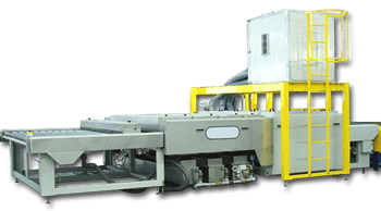
- Inlet conveyor rollers are covered with vulcanized and rectified rubber. It is chain driven.

- A pre-washing unit is installed right above and across inlet roller conveyor. It is used to remove waste or recycle apart or to direct to water coolant tank of grinding machine, if any.
- Washing section consists of 3 top and 3 bottom cylindrical brushes. There is spraying tubes and nozzles in each cylindrical brush. There are three stainless steel water tanks completed with pumps and filters. The last tank comes with electrical heater to heat up water complete with thermostat. Each water tank corresponds to one pair of cylindrical brush. Water should be de-mineralized. Water purification system is to be provided by Buyer. Water is filtered through cartridge filter. There is an extra stainless steel screen filter on each tank. Sliding tray to recover broken glass, if any, is also fitted. All water tanks are design to facilitate cleaning, maintenance and removal of glass scraps.
- There are 3 top and 3 bottom air knives fed by a high pressure air blower fitted above the machine on an overhead platform complete with ladder for easy maintenance and air filter replacement. The blower is acoustically insulated and comes with air filter.
- Outlet conveyor rollers are covered with vulcanized and rectified rubber. It is chain driven.
Transfer Shuttle
This servo driven shuttle is to bring glass from cutting machine to subsequent CNC grinding machine. The shuttle runs on linear bearings driven by servo motor on precision rack and pinion system. Vacuum cups positions are adjustable according to glass shape.
CNC Grinding Machine
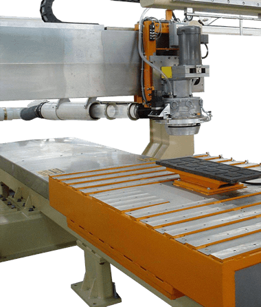
- This 3-axis CNC grinding machine is designed for to edge and polish shape glass such as automotive glass.
- The machine base is fabricated from heavy structural steel for ruggedness and rigidity. In order to remove all stress, the base is normalized after fabrication. The base is then sandblasted, precision machined, drilled and tapped so that it is perfectly fit for other parts and components.
- Mounted on the top surface of rear of base structure are precision linear motion slides which form the "Y" axis. This axis controls the linear motion of the grinding spindle. Linear motion of the slides is controlled by an AC servo motor and a directly coupled, ball type lead screw. The lead screw, in turn, is coupled to the spindle carriage by zero backlash ball screw nuts.
- Mounted to the top surface of front of base structure, perpendicular to the "Y" axis, are precision linear motion slides which form the "X" axis. This axis controls linear motion of vacuum table which holds the glass especially when it is being grinded. Linear motion of this slide is also controlled by a ball type lead screw and zero backlash ball screw nuts which are attached to the work table. Lead screw is powered by an AC servo motor.
- Lead screws on both the "X" and "Y" axes are mounted in pre-loaded, angular contact, high thrust type bearings to eliminate all end play. The linear motion slides on both the "X" and "Y" axes are covered by a pan or guard arrangement to protect them from contaminants. Mounted on the spindle carriage assembly ("X" axis) is a precision grinding spindle directly coupled to a high power AC driven motor.

- The spindle consists of a cylindrical type housing and spindle shaft. Both components are precision machined for accuracy. The spindle shaft and wheel mounting components are balanced to eliminate vibration. The spindle shaft is mounted in the spindle housing on two pairs of Duplex, precision, angular contact, ball bearings installed back to back. Bearings are pre-loaded to eliminate end play. O-ring type seals are used on non-moving spindle parts to protect the spindle bearings. Labyrinth seals are used on the moving parts for protection. The spindle and motor assembly slip into and are attached to an outer housing which is a part of the carriage assembly. The spindle may be removed from this housing by unbolting a clamp ring which secures it to the housing.
- Also attached to the housing that holds the spindle is a vacuum type coolant guard assembly and rotating mechanism. This assembly consists of the necessary components, bearings, seals, gears and an AC servo motor to rotate the guard to keep its slotted opening tangent to the point of grind.
- The vacuum coolant guard also contains a coolant ring which directs coolant to diamond wheel. When grinding, coolant is piped to the ring from an external supply. The guard is also supplied with an outlet to which a vacuum source is attached. This vacuum source causes an inrush of air through the slotted portion of the coolant guard. The inrush of air keeps coolant inside the guard and ultimately returns it to its source through the mist collection system.
- The rotating feature of this assembly comprises the third axis of the machine.
- The diamond wheel is mounted on a motorized, balanced, variable speed spindle; the spindle is fitted with one diamond wheel.
- The CNC electrical cabinet consists of all components necessary to control the system. In the main enclosure is housed the CNC controller, servo amplifiers and an adjustable AC frequency motor drives and other components necessary for manual and automatic operation of the system. The CNC controller is a dual CNC continuous path control that controls the X, Y and Z (coolant guard rotation) axes.
- Servo amplifiers are used to control servo axes motors. Frequency converters are used to control RPM of grinding spindles.
- PLC will control the non-motion functions of the CNC and the shuttle. It will also interface with the line control panel to insure automatic sequencing of the line. In the doors of the panel will be push buttons and selector switches that allow manual and automatic control of the CNC Grinder.
- The machine is equipped with a vacuum coolant guard designed for different diamond wheels diameters. A coolant and mist collection system is equipped to keep coolant off the glass and the machine. The collector consists of a high power vacuum blower and a separation chamber. The air and coolant enter the chamber at the lower third portion of the chamber in a downward direction. The coolant is collected at the bottom of the chamber and air is released out from top. No filter media is required and the mist collection system is enclosed with sound proof material. A coolant drain tank and pump are included. Diamond wheel for test run is to be provided by Buyer.